COMPUTER SCIENCE
УДК 681.3.07
K. K. Aleksanyan
Efficient Implementation of Physical Addressing for
Testing, Diagnosis and
Repair of Embedded SRAMs for Yield Improvement
(Submitted by academician S.K. Shoukourian 23/XII 2005)
Keywords: RAM, memory model,
BIST, redundant element, yield
1. Introduction. Nowadays, System-on-Chips (SoCs) are becoming very much memory dominant.
International Technology Roadmap for Semiconductors predicted that embedded
memories will occupy up to 94% of the total chip area by year 2014 [1].
Furthermore, the memories usually are the densest part of the chip, thus are
more prone to manufacturing defects than other cores on the SoC. As a result,
the overall SoC yield is dominated by the memory yield. Due to the fact that
memory yield decreases and the number of memories increases the overall yield
becomes unacceptable. Detection of faults, diagnosis and repair are a must for
today’s memory designs [2]. Due to shrinking of geometry in the memory array,
new defect types appear that are not screened by conventional March test
algorithms [3]. The defects mostly depend on the design of memory array,
specifics of the manufacturing technology and are sensitized only during some
access conditions. The simple memory model consisting of memory cells that are
organized into rows and columns can not serve well for testing, diagnose and
repairing of today’s memory instances with their complicated architecture, and
more complicated defects that exist on them. Conventional March test consists of
March elements that are applied to the memory array with a certain direction
(incrementing/decrementing) of any sequence. The fault classes (see [4]) they
were designed for were sensitized with any sequence of addresses, thus
incrementing/decrementing address bus value from 0 to maximal address guaranteed
the detection of faults of certain type. Today there exist faults that cannot be
detected by any logical address sequence. They require specific physical
sequence of memory cells that the March element must be applied to sensitize the
fault and detect. Some fault classes of weak cells require marching on memory
cells with physical incrementing/decrementing sequence (see [4]). Other March
tests are proposed (see [3]) to run for some class of delay coupling faults,
that require the physical sequence of memory cells with increment two [5]. After
detection of a fault it is very important to have knowledge about the physical
neighborhood of the faulty cell for further diagnosis. To implement an efficient
BIRA algorithm it is very important to take into account the physical locations
of faulty cells. The simple memory model does not provide all the necessary
information that is vital for today’s complicated designs. Even if a memory core
provider has information about the physical structure of the memory instance
(memory row, column, bank decoding, I/O sequence, etc.), this information can be
useless as usually memory BIST and/or BIRA engines are provided by another core
provider. This paper suggests a novel approach for creating a new memory model
which will include information about the memory physical structure, and allow
working (testing, diagnosing and repairing) with the memory taking into account
all the memory specific information without concerning about physical structure.
For example, for hardware implementation of a BIST engine that uses physical
addressing, a converter can be used that transforms physical address into
logical address. This kind of modeling of a memory is very useful as test and
repair processor compilers are widely used for supporting memory systems with
various types and configurations of memory instances. The memory model
description can be used for generation of mentioned converter’s Register
Transfer Level (RTL) description.
In the following we will discuss the proposed
memory model description, how it can be used for memory test coverage
improvement, how memory model description can bring to better understanding of
memory defect distribution and may be to its main cause, how to use physical
fault map for improving repair yield.
2. Memory model description. In this section we will discuss bit-oriented memories, but it can easily
be generalized for word-oriented memories. Let us define what a memory is for
its users. Memory is an array of bits and each bit has its unique address. The
user has a very simple interface to work with the memory. The interface includes
read and write operations with a given bit address. Memory uses address bus as
an input and data in/out pin(s) for read and write operations. In general the
user does not know physical location of a bit in the memory array for a given
address. Thereafter we will use "logical" address for the one that is applied to
memory address bus. This interface is enough for an application that uses the
memory as storage, but it is far from being sufficient for efficient memory
test, diagnose or repair engines. It does not provide information about mapping
from logical address to physical location of the bit that is accessed. If the
test wants to access the bottom-most row of memory bit-cell array, or wants to
march on physically neighboring bit-cells it can never do that with this simple
interface. As a result we have demand to enlarge the memory model. Memory core
provider needs to describe how the logical address to physical location mapping
engine works. This mapping engine can be provided as a function that takes
logical address as an input and outputs physical location of a word. If we go
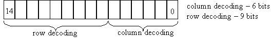
deep into memory architecture we will see that different decoding engines work
for rows and columns. The logical address is split into two halves; one is the
input for row and the other for column decoding engines, see Fig. 1. If we want
to have a better imagination about the memory physical structure our function
should take the logical address (also the bit number of a bit-cell, for
word-oriented memories) as an input and output the physical row and column
positions of the cell. Most of test applications need the opposite conversion
from physical location to logical address. If our memory model description has a
function that will return the range of address bus positions used for row
decoding (obviously the range of address bus positions used for column decoding
can be extracted using the same function) then the logical address can be split
into two parts: logical row address and logical column address. Thus we propose
to use two functions to describe physical to logical mapping, the first one will
take physical row number and return logical row address, and the second one will
take physical column number and return logical column address.
|
|
Figure 1:
Memory test algorithms usually apply some
background pattern to memory array and then try to read it. In case of
mismatching the pattern, a fault is reported. It is shown that test algorithm
defect coverage, defined as the proportion of detected faults defects to
existing defects, is highly dependent (up to 30%) on the background pattern it
applies to the memory array [6]. There are several categories of background
patterns:
- Logical background
pattern; that is applied to memory through logical addresses. Example: write
zero for even addresses and one otherwise.
- Physical
background pattern; that is applied to memory, based on physical locations.
Example: write zero for the bit-cells that are located on even columns and one
otherwise.
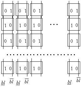
- Topological
background pattern; that is applied to memory, based on cell bit-lines. Example:
write a value to guarantee zero value on the bit-lines that are on even
positions and one on the bit-lines that are on odd positions.
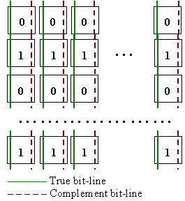
Figure 2:
Another example of topological background pattern is the checkerboard pattern
that is applied to memory bit-lines (see Fig. 2). To apply such a background
pattern it is necessary to know which bit-line of each cell is the True bit-line
(wire holding the value of cell) and which one is the complement bit-line (wire
holding the inverted value of cell). Thus for higher fault coverage we need to
add another component to our memory model: memory "bit-line mirroring"
information. This information will be provided by another function that will
take the physical location of a memory bit-cell (physical row, column) and
return a Boolean value indicating if True bit-line is the left bit-line and
Complement bit-line is the right bit-line or vice-versa. We can apply any
topological background pattern based on the specified function (see Fig. 3.).
Figure 3:
After fabrication of dies with failing
memories some diagnostic processes, that are called to enhance the further
yield, require knowledge of physical location (not column/row number, but X/Y
coordinates) of failing bit(s) to find out the main cause(s) of defects. The
simple memory model does not give information about how the cells are
distributed and how the memory logic is distributed within the memory cell array
(rows/columns). This information is vital to do required diagnosis. An advanced
memory model should provide the physical distribution of straps with memory
logic elements, their dimensions as well as memory bit-cell dimensions. Suppose
a function returning a list of records about the straps of the memory instance.
The record should contain the strap location (row/column number it is located
at) and its dimensions. Another parameter can be provided with bit-cell
dimensions. It seems that having bit-cell width and height, straps’ distribution
and width/height values as well as logical to physical mapping functions it is
quite possible to calculate the coordinates of any required bit-cell, but if we
look deep into the memory instance layout picture we will see dummy cells and/or
redundant elements (rows/columns) besides the main memory cell array and memory
logic blocks. In order to do have correct calculations our memory model must
contain information about the distribution of these elements. This brings to the
necessity of another memory model description component.
3. Hardware implementation of
physical address generator for built-in self-test engine. In a
conventional test model we have external tester that applies test patterns to an
Integrated Circuit (IC). Particularly external tester can be used to run a test
algorithm for a memory instance. Having the appropriate memory model description
it will not be difficult to apply a test algorithm in such a way which will
guarantee the required addressing for the physical memory array and background
pattern. But because using external testers for today’s SoCs is extremely
expensive Built-in self-test (BIST) solution is widely used for testing memory
cores [7]. For this case the problem is a little complicated, as BIST engine
must have all the physical structural information built-in about the memory
instance it is going to test. The BIST engine provider can take that information
into account during the BIST engine design step. But if we look deep into
today’s architecture [2] we will see that BIST engine is not designed to test a
single memory instance but a number of memory instances with different
configurations and different logical to physical mappings. In today’s SoC design
a whole infrastructure exists [8] called Memory System with self-test and repair
processor and integrated wrappers for each memory instance that exist in the
Memory System. Memory Systems are not designed for each particular design.
Software Compilers exist that compile RTL description of a Memory System to
support a given set of memory instances. If the memory model description is
present at the compile stage of the Memory System the compiler can compile a RTL
converter as a part of the address generator module of the integrated wrapper
and the generated Memory System will have possibility to use this converter
during self-test or for further processes. Memory System compiler uses templates
to generate different RTL modules, based on the memory configuration parameters
and Memory System parameters. If the memory model description exists, with a
given format, the corresponding template will generate physical to logical
converter module based on that description and configuration parameters.
|
|
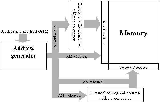
Figure 4:
The synthesis showed that the corresponding
RTL does not occupy more then 0.5% of the overall self test and repair engine
after synthesis. The more advanced memory system compilers give possibility for
programmable test algorithms. The user can select the parameters of a memory
system (soft repair or hard repair, sequential or parallel test for memory
instances, etc.) as well as the test algorithm for running the built-in test.
For March tests usually the user specifies the direction of March element,
addressing step the test has to march over the memory array. Having the logical
to physical converter module in place (see Fig. 4), the user will be able to
specify the addressing method of each March element, thus create more flexible
test algorithms for higher fault coverage.
Resistive bridges and opens (see [3]) lead to
several dynamic fault behaviors that bring to timing related failures. The well
known March tests do not cover delay coupling faults without inserting special
delay elements into the test algorithm. Sometimes these inserted delays last
more than the entire test time is. Special March tests are developed (see [5])
to detect timing related failures without the delay elements. These test
algorithms use physical row addressing and logical column addressing. The
suggested implementation of the physical address generator will allow
programming of specified test algorithms.
4. Memory model description for
fault diagnosis. Conventional March test algorithms are very useful for
detection of failing bit-cells. Most of the March test algorithms provide fault
dictionaries [9], allowing to specify the functional fault model based on the
set of indexes (called fault syndrome [9]) of read operations that caused
mismatch between written and read values. But detection of failing bit-cell and
the fault type are quite not enough for yield enhancement. After repair of a
failing bit-cell it is not unusual to detect another failing bit with the same
functional syndrome, if a coupling fault [9] caused the failure. The reason is
that we repair the victim cell (the cell where the fault appears), while the
main cause of the failure was the aggressor cell (the cell that is sensitized)
[9]. To give a solution to this problem we need somehow detect the aggressor
cell. After detection of a failure in a victim cell, we must do further analysis
to locate the aggressor cell. For this reason many test algorithms contain
March-like elements for diagnosis purpose [9]. Much work was done in this sphere
(see [9-11]), most of them propose test algorithms that march on the
neighborhood (as the aggressor cell is located on the neighborhood of the victim
cell with high probability) of the victim cell to find out which cell has an
impact on it. For a simple memory model it is quite difficult to select the
neighborhood address space of the victim cell, instead of that the diagnosis
portion of the test algorithm must march through all address space in order to
find the aggressor cell. Giving the physical to logical converter to test
engine, we can strongly reduce the test time. It allows increment the physical
row and/or column number (march through the neighborhood of the victim cell) of
the victim cell and the converter will help to access the cell with an
appropriate logical address.
5. Physical fault map and BIRA
yield improvement. Built-in repair algorithms are widely used in today’s
test & repair infrastructures. The more is the BIRA repair coverage the
higher is the memory yield. The more is area overhead occupied by BIRA circuit
the less is the overall yield. That is why it is very important to have a BIRA
with higher repair coverage and with less area overhead. Much work was done on
this topic (see [2]).
Redundant column and row macros (consisting
several physical rows/columns) are widely used in BIRA algorithms. Thus
replacing a faulty row/column with redundant row/column we also replace some of
the neighboring rows/columns of the faulty row/column. It is very important to
know the logical address space of the replaced array, not to duplicate the usage
of redundant resources in case of detecting the second fault in the replaced
logical address space. We propose to use information about the redundant element
width (number of physical rows/columns it is consistent) and already mentioned
physical to logical converter by BIRA circuit to increase the BIRA repair rate.
Yield, defined as the proportion of
operational circuits to the total number of fabricated circuits [11], of
repairable memories is highly dependent on repair rate:
Yar = Ybr + (1 - Ybr)
* R,
where Ybr - is the yield of memory before repair, R - is the repair
rate and Yar - is the yield after repair. We have used negative
binomial defect distribution [11] for some experimental yield calculations:
Ybr = (1 + [(l)/(a)])-a where l - is the average
number of defects and a - is the clustering parameter.
We have considered five SoC designs with 400 memory instances each, one
redundant row and one redundant column was assigned to each memory instance. The
memory instances are taken with different Number of Words (NW), Number of Bits
per word (NB) and Column-Mux (CM). Table 1 shows the yield increase and area
overhead of SoC if we take into account the physical structure of the memory.
The yield increase is about 0.85%, and area overhead is about 0.4%.
Table 1
| SoC |
Num. instances |
NW |
NB |
CM |
Yield increase (%) |
Area overhead (%) |
| 1 |
400 |
1024 |
16 |
32 |
0.87 |
0.38 |
| 2 |
400 |
512 |
32 |
16 |
0.86 |
0.41 |
| 3 |
400 |
256 |
64 |
8 |
0.85 |
0.39 |
| 4 |
400 |
128 |
128 |
4 |
0.85 |
0.38 |
| 5 |
400 |
64 |
256 |
2 |
0.81 |
0.36 |
6. Conclusion. An
efficient way for automated generation of SMS is proposed with physical
addressing. A physical to logical converter is introduced into SMS for the test,
diagnosis and repair engines to take into account the memory physical structure
and improve the SMS yield significantly. The proposed approach has been
implemented and verified for several memory compilers. Experimental results
showed significant yield improvement at low hardware overhead.
Yerevan State University
Литература
1. ITRS 2001,
http://public.itrs.net/
2. Y.
Zorian, S. Shoukourian "Embedded-Memory Test and Repair:
Infrastructure IP for SoC Yield",
D&T2003.
3. M. Azimane, A.
Majhi, G. Gronthoud, M. Lousberg, S. Einchenberger, A. Lloris Ruiz "New Algorithm for Dynamic Faults Detection in RAMs", VTS
2005.
4. S. Hamdioui, A.J. van de
Goor, M. Rodgers, "March SS: a test for all static simple
faults", Records of IEEE Int. Workshop MTDT, 2002, pp.
95-100.
5. Mohamed Azimane
"New Algorithm for Dynamic Faults Detection in RAMs",
VTS2005.
6. Ad. J. van de Goor,
Ivo Schanstra "Address and Data Scrambling: Causes and Impact
on Memory Tests" Delta 2002.
7. Y. Zorian, "Embedded memory test & repair:
Infrastructure IP for SOC yield", ITC 2002.
8.
S. Shoukourian, V. Vardanian, Y. Zorian, "SoC
yield optimization via an embedded-memory test and repair infrastructure", IEEE
Design & Test of Computers, May-June
2004.
9. G. Harutunyan, V.A.
Vardanian "Minimal March-Based Fault Location Algorithm with
Partial Diagnosis for Random Access Memories", CSIT
2005.
10. V. A. Vardanian, Y.
Zorian, "A March-based Fault Location Algorithm for Static
Random Access Memories", Proc. IEEE Int. Workshop MTDT,
2002.
11. Israel Koren, Zahava
Koren "Defect Tolerance in VLSI Circuits: Techniques and
Yield Analysis" Proceedings of the IEEE 2005.